You mount a three-phase Solid State Relay on a panel, wire it to a heater bank, and move on to the next cabinet. Six months later the relay fails—not because the load was too high, but because the heat it generated had nowhere to go. A Solid State Relay dissipates roughly 1 to 1.2 watts per ampere of conducted current at its baseplate, and a 100A three-phase unit can shed over 100W as heat. This article explains where that heat comes from, how thermal resistance determines whether the relay survives, and what to verify when you pair a 10–100A three-phase relay with an XH-series heat sink.
How Much Heat Does a Relay Actually Produce?
Watt Loss Per Ampere
The on-state voltage drop across a relay’s output semiconductors is typically between 1 and 1.6V. Multiply that drop by the conducted current, and you get the watt loss. A manufacturer’s rule of thumb puts it at 1.5W per ampere for sizing purposes, which already includes a margin over the 1–1.2W/A figure.
For a 40A load on each of three phases, the continuous dissipation can reach 60–72W inside a single relay package. That energy has to leave through the metal baseplate, and if the baseplate can’t shed it, the junction temperature climbs.
Why the Baseplate Sets the Limit
The relay’s internal junction has a maximum temperature, and the baseplate is the only practical path for heat to escape. A commonly cited acceptance criterion is keeping the baseplate at or below 75°C. Some relay manufacturers recommend an even tighter 65°C baseplate limit under test conditions. Once the baseplate crosses that threshold, the junction temperature margin disappears, and the semiconductor switch degrades or fails.
The heat sink’s job is to hold the baseplate below that limit across the full range of ambient temperature and load current.
What Does Thermal Resistance Tell You About a Heat Sink?
The °C/W Rating Explained
Thermal resistance, expressed in °C per watt, describes how much the heat sink’s temperature rises above ambient for every watt it dissipates. A 1.9°C/W heat sink carrying 60W of heat will sit roughly 114°C above ambient at steady state—which is why heat sink selection starts with the watt load, not the relay’s current label.
Lower thermal resistance is always better. A 1.5°C/W sink sheds the same wattage with a smaller temperature rise than a 1.9°C/W sink. But lower resistance usually means more aluminum, more fins, and more cabinet space.
Reading the Derating Curve Instead of Guessing
The practical way to match relay to heat sink is the manufacturer’s derating curve. The curve plots continuous load current against ambient temperature, with a separate line for each heat sink thermal resistance. You find your operating current on the vertical axis, your worst-case panel temperature on the horizontal axis, and where those two values intersect tells you the maximum °C/W your heat sink can have.
Two mistakes are common at this step: using normal ambient temperature instead of the maximum the panel will see, and ignoring inrush current from inductive or capacitive loads. Both push the intersection point toward a lower thermal resistance—a bigger heat sink than the first calculation suggested.
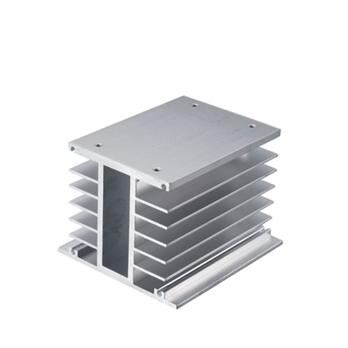
| Parameter | XH-110 | XH-132 | XH-150 |
|---|---|---|---|
| Dimensions (L×W×H) | 110×80×80mm | 132×80×80mm | 150×80×80mm |
| Thermal resistance | 1.9°C/W | Lower than XH-110 | Lowest of the three |
| Suitable relay range | 10A to 100A | 10A to 100A | 10A to 100A |
| Material | Anodized aluminum | Anodized aluminum | Anodized aluminum |
How Does Ambient Temperature Change the Required Sink?
From 40°C to 60°C: A Real Derating Example
A relay rated 100A at a 40°C reference ambient doesn’t carry 100A at 60°C. With a temperature compensation coefficient of 0.86 applied to the reference rating, the permissible operating current drops to 86A at 60°C. The heat sink selection has to follow that derated current, not the nameplate number.
Inside a closed control cabinet near ovens, furnaces, or large drives, the internal ambient can easily reach 55–65°C even when the room is air-conditioned. That’s why panel builders size heat sinks against the maximum internal cabinet temperature, not the plant floor temperature.
Natural Cooling, Forced Air, and the 40A Threshold
A common installation rule splits heat sink strategy by current: below 5A, free-air cooling may suffice; above 10A, a heat sink is mandatory; above 40A, forced ventilation or fan cooling becomes necessary. The XH series covers the 10–100A band with passive extruded aluminum sinks, but at the upper end of that range—especially in a warm cabinet—an enclosure fan or filtered ventilation may be required to hold the baseplate below 75°C.
What Mounting Details Decide Thermal Performance?
Thermal Pad Thickness and Surface Flatness
The interface between the relay baseplate and the heat sink is a thermal bottleneck. A thermal pad or thermal compound is required, and a layer thickness of 0.006–0.008 inches (0.15–0.20mm) is the recommended range. Too thin and the surfaces don’t fully contact; too thick and the interface adds unnecessary thermal resistance.
The heat sink mounting surface should be flat, clean, and free of paint or heavy anodize buildup on the contact face. Anodized aluminum is acceptable as a heat sink material, but the anodized layer itself adds a small thermal resistance that should be accounted for in critical applications.
Screw Torque and Even Pressure
The relay’s mounting screws must be tightened evenly so the baseplate presses flat against the heat sink. Uneven torque creates a tilted baseplate with an air gap on one side—effectively reducing the contact area and raising the interface thermal resistance. A loose screw also increases electrical resistance at the power terminals, which compounds the heating problem.
Check the relay datasheet for the recommended mounting torque, and use a calibrated driver rather than tightening by feel. For three-phase relays with a long baseplate, tighten in a cross pattern to seat the plate evenly.
Where Does Thermal Mismatch Show Up First?
Nuisance Trips, Shortened Life, and Silent Failures
The first symptom of an undersized heat sink isn’t always a dead relay. It’s often a relay that runs hot enough to trip a thermal protection circuit, or one that fails prematurely after a few months of seasonal temperature swings. In dense panels with multiple relays mounted side by side, the heat from adjacent units raises the local ambient, pushing each relay closer to its limit.
A Solid State Relay that switches heater loads, motor starters, or transformer primaries also sees inrush current well above the steady-state rating. The heat sink has to be sized for the thermal equivalent of that duty cycle, not just the continuous current printed on the load schedule.
Matching the Sink to the Relay Family
A 1.9°C/W heat sink is appropriate for lower-current three-phase relays in moderate ambient. As the current approaches 75–100A per phase, or as the cabinet temperature climbs above 50°C, stepping up to the XH-132 or XH-150 with lower thermal resistance provides the margin needed to keep the baseplate under 75°C. The XH series is designed for 10–100A three-phase Solid State Relay mounting, with anodized aluminum extrusion and a footprint that fits standard panel layouts.
Straight Answers on Relay Heat Sink Selection
Can I run a 100A relay without a heat sink?
No. A relay carrying more than a few amps in continuous duty needs a heat sink. The exact threshold depends on the model, duty cycle, and ambient temperature, but above 10A a heat sink is effectively mandatory, and above 40A passive cooling alone often isn’t enough. Running a 100A relay bare will drive the baseplate past its limit even at modest load.
What thermal resistance do I need for 40A per phase?
Use the derating curve. At 40A continuous and a 50°C panel ambient, many three-phase relays require a heat sink in the 1.5–2.0°C/W range. The XH-110 at 1.9°C/W fits that operating point; if the panel ambient reaches 60°C, the same current pushes the requirement toward a lower °C/W value, which the larger XH models address.
Does a bigger heat sink always solve overheating?
Not always. If the cabinet has no airflow and the heat sink is boxed in by wiring ducts, the aluminum can’t exchange heat with the surrounding air. Forced ventilation, filtered fans, or relocating the relay to a cooler section of the panel may be necessary even with a large sink. Thermal management is a system problem—heat sink, interface, airflow, and mounting all contribute.
How do I verify the installation after commissioning?
Run the relay at its actual load and duty cycle for a sustained period, then measure the baseplate temperature with a contact thermometer or thermal camera. If the baseplate stabilizes below 75°C—and preferably below 65°C for margin—the heat sink and mounting are adequate. Repeat the measurement at the highest expected summer ambient, not just on a comfortable day.
Let's Match an XH Heat Sink to Your Three-Phase Relay
Share Your Current, Ambient, and Panel Layout
A Solid State Relay survives on the thermal path you build around it. The XH Three-phase SSR heat sink from Xuruien is an anodized aluminum extrusion rated at 1.9°C/W on the XH-110, with the XH-132 and XH-150 providing lower thermal resistance for higher-current or higher-ambient installations. The series covers the 10A to 100A three-phase range and mounts with a thermal pad for a controlled interface. If you’re sizing heat sinks for heater control, motor switching, or transformer loads, send us your per-phase current, maximum panel ambient, and available mounting space — we’ll help you confirm the right XH model before you mount the relay.