Have you ever had a button or limit switch fail just weeks after installation? You are not alone. A logistics automation provider recently replaced 120 end-of-stroke switches in six months because the chosen parts could not handle the vibration and inrush current of their conveyor system. The root cause was rarely a manufacturing defect—it was a mismatch between the switch’s real capabilities and the application’s demands.
Selecting a reliable snap-action switch does not have to be a gamble. By following a structured five-step process, you can avoid costly retrofits and keep your production lines running. Below is a framework used by maintenance leads and design engineers who need consistent performance without over-engineering their BOM.
Define Your Electrical Load – Beyond “15A.”
The first and most overlooked mistake is treating the contact rating as a fixed number. A switch rated for a 15A resistive load may fail quickly on a motor or solenoid load because of inrush current. For inductive or capacitive loads, the initial surge can be 5 to 10 times the steady-state current.
Ask yourself three questions:
-
What is the steady-state current?
-
What is the inrush current?
-
Is the load resistive, inductive, or capacitive?
For motor-driven equipment, always derate the switch by 30–50% from its resistive rating. If you are unsure about inrush calculations, review common electrical rating guidelines for micro switches before moving to mechanical fitting.
Match Environmental Protection – Dust, Moisture, and Temperature
Environmental factors cause more switch replacements than electrical failures. A clean, dry indoor panel is very different from a food packaging line with daily washdowns or an outdoor gate exposed to freezing rain.
Check these four parameters against your operating environment:
-
Ingress Protection (IP) rating – IP40, IP67, or IP69K
-
Operating temperature range – Standard: -25°C to +85°C; extended: -40°C to +125°C
-
Contact material – Silver alloy vs. gold-plated
-
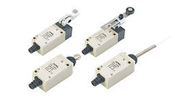
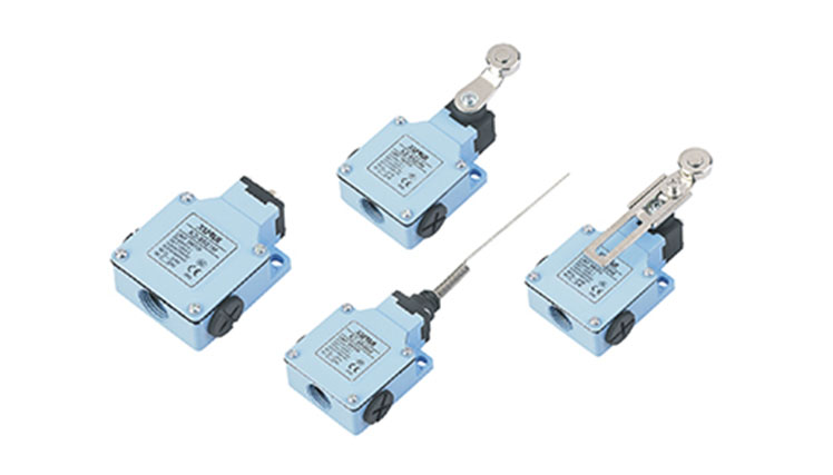
Sealing type – Pin plunger, roller lever, or sealed plunger with rubber boot
For high-humidity or outdoor applications, a sealed actuator design significantly reduces oxidation. Many engineers switch to potted or epoxy-sealed bases when previous units showed corrosion within 12 months. If your application involves frequent temperature cycling, explore sealed actuator options and their performance data to avoid condensation-related failures.
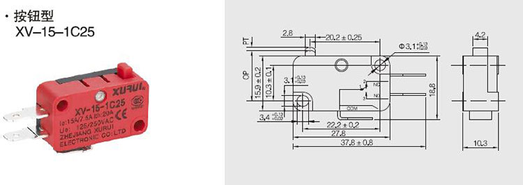
Verify Mechanical Fit – Actuator, Mounting, and Overtravel
This is where detailed dimensions matter more than the datasheet’s headline numbers. A switch may have perfect electrical specs but fail mechanically because the actuator does not align with the cam, or the mounting holes are 0.5mm off.
Five mechanical checks to perform:
-
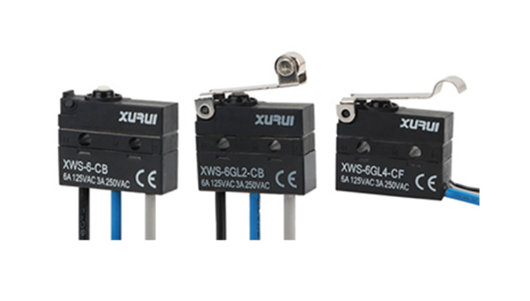
Actuator type – Pin plunger, hinge lever, roller lever, or simulated roller
-
Pretravel (PT) – Distance from free position to operating position; too short risks false triggering
-
Overtravel (OT) – Distance after operating position before hard stop; essential for absorbing cam over-travel
-
Operating force (OF) – Force required to trip the mechanism
-
Mounting hole pitch – Common: 25.4mm or 22.2mm center-to-center
A common field failure: using a pin plunger on a rotating cam, causing side loading and premature lever breakage. For rotary or sliding motions, a roller lever type extends life by converting friction into rolling contact. Always request a 2D drawing with the full mechanical travel limits before finalizing panel layout.
Check Safety and Agency Approvals – UL, ENEC, CQC
Certifications are not just for compliance—they are shortcuts to proven reliability. A switch approved by UL, ENEC, or CQC has passed standardized endurance, dielectric strength, and flame resistance tests that many uncertified components skip.
Critical certifications based on your market:
-
North America – UL 61058-1 or UL 1054
-
Europe – ENEC with VDE mark preferred
-
China – CQC
-
Global – CB scheme
Do not assume a generic “UL recognized” component automatically fits your end-product certification. Verify the specific “File Number” and “Rating conditions”. Some switches carry only a basic UL listing for resistive loads, which excludes motor or tungsten lamp loads. If your device requires a particular safety class, review certification details for industrial micro switches before ordering samples.
Test Lifecycle Under Actual Conditions – Not Just Datasheets
The datasheet mechanical life often misleads because it is measured without load. Electrical life at rated current is typically 50,000 to 500,000 cycles—a huge range. The only way to know is by testing or relying on documented third-party results.
Three practical approaches:
-
Ask for test reports – Reputable suppliers provide load-life curves
-
Run a pilot batch – Install 10–20 switches on your actual machine for 2–4 weeks of production
-
Check failure modes – Welded contacts, pitted contacts, or broken spring
One automation integrator we work with reduced its annual switch replacement cost by 62% after switching from a generic 15A model to a unit with documented electrical life at 10A inductive load. The winning configuration used a fine-silver contact with a double-break mechanism, which extinguishes arcs faster than single-break designs.
If your application requires high repeatability, pay special attention to operating position tolerance.
Common Misconceptions That Cause Selection Errors
“Higher current rating always means better.” False. A high-current switch may have stiffer springs, increasing operating force and reducing actuator life in low-torque cam systems.
“All roller levers are the same.” False. Roller diameter, material, and mounting orientation affect wear. Plastic rollers run quieter but wear faster on rough cams.
“Sealed switches never fail from contamination.” Partially true, but seals age. Silicone rubber boots last ~5 years in UV exposure; epoxy-sealed bases outlast them but cannot be disassembled for cleaning.
Final Recommendation – When to Move from Selection to Sourcing
After completing these five steps, you will have a shortlist of switches matching your electrical, environmental, mechanical, and certification requirements. The next decision is balancing unit cost against total installed cost. A switch that costs $0.50 less but requires twice the field service visits is never cheaper.
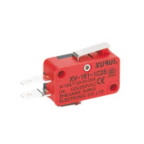
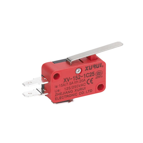
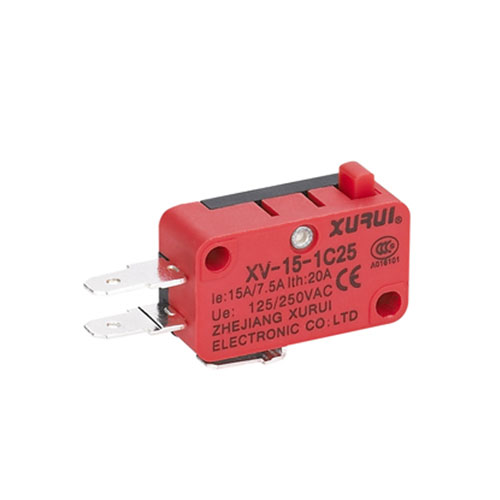
For many industrial and appliance applications, the sweet spot is a 15A-rated snap-action switch with silver-alloy contacts, a sealed plunger, and UL/ENEC/CQC approvals. This configuration handles most motor, solenoid, and heater loads while surviving dust and humidity. One family that meets these criteria is the XV-15 series, which offers multiple actuator styles and terminal options. However, always verify the exact part number against your load profile and mounting dimensions.
If you want to reduce selection risk and get a switch that has been field-validated across packaging, HVAC, and access control systems, take a look at Xurui’s catalog. Their technical team provides load-life test summaries and can recommend a specific actuator based on your cam design—saving you from the “test three, fail two” cycle.
Disclaimer: Electrical load characteristics vary by application. Always verify with real-world testing under maximum expected conditions. This guide provides general selection principles and does not replace certified engineering judgment.