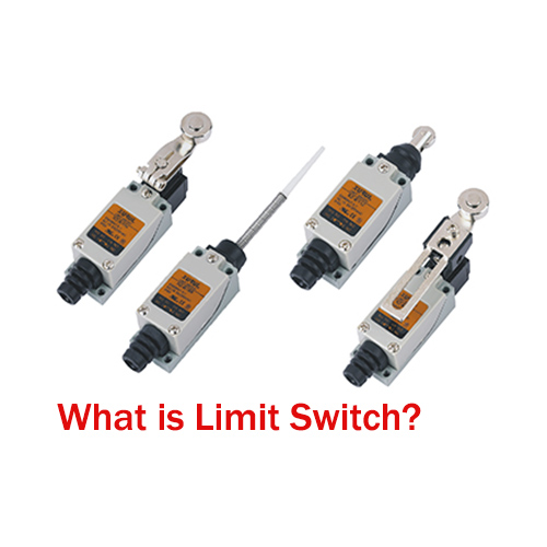
Limit switches are essential sensing and control devices widely used in industrial automation, machinery protection, and HVAC equipment. They detect the presence, position, or movement of an object and trigger an electrical response to ensure safe and accurate operation. Understanding how limit switches work helps users improve system reliability, prevent equipment damage, and maintain safe operation.
What is the Function of a Limit Switch?
The primary function of a limit switch is to detect mechanical movement and convert it into an electrical signal. When a machine part or object touches the actuator of the limit switch, the internal contacts change state—either opening or closing the circuit.
Its main roles include:
-
Position detection of moving parts
-
End-of-travel control, ensuring machinery stops at a safe point
-
Safety interlocking to prevent hazardous operation
-
Counting and monitoring repetitive machine cycles
-
Overtravel or overload protection in HVAC and industrial systems
Core Working Principle
The core working principle of a limit switch revolves around the interaction between a mechanical actuator and an internal electrical contact mechanism. When an external force acts on the actuator of the limit switch, it causes a mechanical displacement, which in turn changes the state of the internal electrical contacts—either opening or closing the circuit.
Here is a step-by-step breakdown of the process:
1. Mechanical Actuation: The target object comes into contact with the actuator of the limit switch. The actuator is typically a lever, roller, plunger, or whisker that is designed to move when subjected to external pressure.
2. Internal Mechanism Movement: The movement of the actuator is transmitted to the internal mechanism of the switch, which may include springs, cams, or levers. This transmission amplifies or directs the force from the actuator to the electrical contact assembly.
3. Contact State Change: The internal mechanism causes the electrical contacts to shift position. Most limit switches have normally open and normally closed contacts. In the resting state, the NC contacts are closed, and the NO contacts are open. When actuated, the NC contacts open, and the NO contacts close—interrupting one circuit and completing another.
4. Electrical Signal Output: The change in contact state generates an electrical signal that is sent to the control system. The control system then responds to this signal by executing the predefined action, such as stopping a motor, activating an alarm, or starting another process.
5. Reset: Some limit switches are "momentary," meaning they return to their original state once the external force on the actuator is removed. Others are "maintained" or "latched," and require a separate reset action to return to the resting state.
Key Components & Types
Key Components
A typical limit switch consists of several essential components that work together to achieve its function:
Actuator: The external part of the switch that comes into direct contact with the target object. Common types include lever actuators, plunger actuators, whisker actuators, and rotary actuators.
Contact Assembly: The internal electrical part that controls the circuit. It includes fixed contacts and movable contacts. The movable contacts are connected to the actuator mechanism and shift position when the switch is actuated. The contacts are usually made of conductive materials like copper or silver alloy to ensure good electrical conductivity.
Mechanism Housing: A protective casing that encloses the internal components, shielding them from dust, moisture, vibration, and other environmental factors. The housing is often made of durable materials such as plastic, metal, or stainless steel, depending on the application environment.
Springs: Used to provide the restoring force that returns the actuator and contact assembly to their original positions after actuation. Springs also help maintain the contact pressure to ensure reliable electrical connections.
Terminal Connections: Points where the limit switch is wired to the control system or power supply. These terminals are typically labeled to facilitate proper wiring.
Common Types of Limit Switches
Plunger Limit Switch: Uses a push-button style actuator for linear detection.
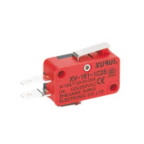
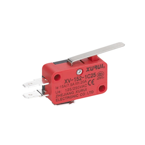
Roller Lever Limit Switch: A lever with a roller detects sliding or rotating motion.
Rotary/Adjustable Arm Limit Switch: Ideal for conveyors, hoists, and rotating equipment.
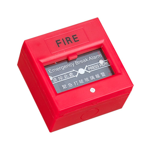
Safety Limit Switch: Designed for doors, guards, and emergency interlocks.
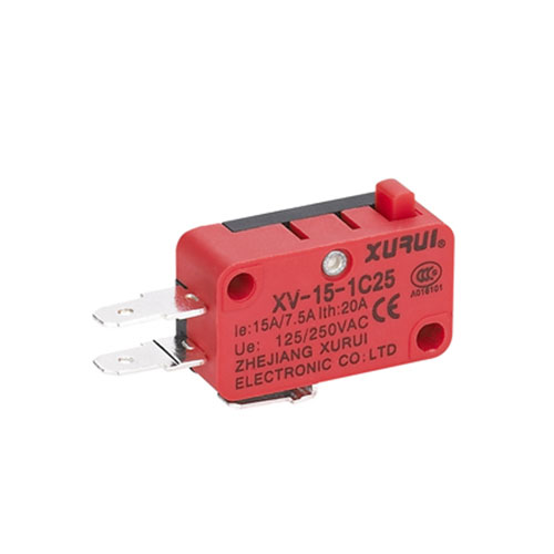
Micro Limit Switch: Compact, sensitive, and widely used in appliances, electronics, and automation.
Can you run a furnace without a limit switch?
Running a furnace without a limit switch is not recommended and extremely dangerous. In a furnace system, the limit switch serves as a critical safety device designed to prevent the furnace from overheating, which can lead to fires, carbon monoxide leaks, or catastrophic equipment failure.
Here’s why the limit switch is indispensable for a furnace:
-
Overheating Protection: The limit switch monitors the temperature inside the furnace’s heat exchanger. If the furnace’s burners continue to operate without proper airflow, the heat exchanger can overheat. When the temperature reaches a dangerous threshold, the limit switch trips—shutting off the gas supply to the burners and stopping the heating process.
-
Prevention of Fire Hazards: An overheated heat exchanger can crack, allowing flammable gases or flames to escape into the furnace’s cabinet or the surrounding structure, increasing the risk of a house fire.
-
Carbon Monoxide Safety: A cracked heat exchanger (caused by overheating) can also allow carbon monoxide (a colorless, odorless, and toxic gas) to leak into the home, posing a serious health risk to occupants.
-
Equipment Longevity: Continuous overheating can damage other furnace components, such as the blower motor, control board, and burners, leading to costly repairs or premature replacement of the entire furnace.
Conclusion
Limit switches are fundamental safety and control components that detect mechanical movement and convert it into electrical signals. Their working principle is simple yet highly reliable, making them indispensable in industrial machinery, automation systems, and HVAC equipment. With various types and robust design, limit switches ensure accurate position sensing, safe operation, and effective temperature protection—especially in critical applications like furnace control.
FAQ
Q1: How do I know if a limit switch is faulty?
A: Common signs of a faulty limit switch include: the system stopping unexpectedly or failing to start; the switch not tripping when it should; or the switch tripping repeatedly without a clear cause. You can test it with a multimeter to check if the contacts are opening/closing properly when actuated.
Q2: Can limit switches be used in outdoor environments?
A: Yes, but you need to choose waterproof or dustproof limit switches with appropriate IP ratings. These switches have sealed housings that protect internal components from rain, snow, dust, and humidity.
Q3: What is the difference between a limit switch and a proximity sensor?
A: A limit switch is electromechanical and requires physical contact with the object to actuate. A proximity sensor is non-contact and detects objects using magnetic fields, radio waves, or sound waves. Limit switches are simpler and more durable in harsh environments, while proximity sensors are better for high-speed or non-contact applications.
Q4: How often should limit switches be maintained?
A: Maintenance frequency depends on the application environment. In general, industrial limit switches should be inspected quarterly—cleaned of dust/debris, checked for loose wiring, and tested for proper actuation. In household appliances, annual inspection during routine maintenance is sufficient.