1. What Is a Solid-State Relay (SSR)?
A solid-state relay (SSR) is an electronic switching device that uses semiconductor components (such as thyristors, transistors, or TRIACs) to control the flow of current in a circuit. Unlike traditional mechanical relays, SSRs have no moving parts, enabling faster switching, silent operation, and enhanced durability. They are widely used in industrial automation, temperature control systems, and applications requiring high-speed cycle control.
2. Structure and Operating Principle
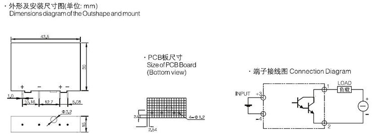
An SSR consists of three primary components:
Input Circuit: Receives a low-voltage control signal (e.g., 3–32 V DC or AC).
Isolation Element: Optically isolates the input and output using an optocoupler (e.g., LED and photosensitive component) to prevent electrical interference.
Output Switch: A semiconductor device (e.g., TRIAC for AC loads or MOSFET for DC loads) that conducts current when triggered by the input signal.
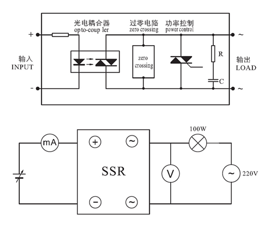
Operating Principle:
When a control voltage is applied to the input, the internal LED emits light, activating the photosensitive component. This triggers the output semiconductor to switch the load circuit on or off. The absence of mechanical contacts eliminates arcing and bounce, ensuring reliable operation.
3. Key Features of Solid-State Relay (SSR)
High Speed: Switching times in microseconds, ideal for high-frequency applications.
Long Lifespan: No mechanical wear ensures millions of cycles.
Silent Operation: No audible clicking.
Low EMI: Minimal electromagnetic interference due to no arcing.
Compact Design: Smaller footprint compared to mechanical relays.
Drawbacks: Higher cost, heat generation under high loads, and potential voltage drop.
4. Mechanical Relays vs Solid-State Relays
| Feature | Mechanical Relays | Solid-State Relays (SSRs) |
|---|---|---|
| Switching Mechanism | Electromagnetic coil + contacts | Semiconductor components |
| Speed | Slow (milliseconds) | Fast (microseconds) |
| Lifespan | 100,000–1 million cycles | 10+ million cycles |
| Noise | Audible click | Silent |
| Shock/Vibration Resistance | Poor | Excellent |
| Power Consumption | Higher (coil power) | Lower (no holding current required) |
| Heat Dissipation | Minimal | Requires heatsinking at high loads |
| Cost | Lower | Higher |
5. Types of Solid-State Relay (SSR)
By Input Signal:
DC-Controlled SSRs: Activated by a DC voltage (e.g., 5V or 24V).
AC-Controlled SSRs: Activated by an AC signal (e.g., 120V or 240V).
By Output Type:
AC SSRs: Use TRIACs or thyristors to switch AC loads (e.g., heaters, motors).
DC SSRs: Use MOSFETs or transistors for DC loads (e.g., solenoids, LEDs).
Three-Phase SSRs: Control three-phase industrial equipment.
By Switching Mode:
Zero-Crossing SSRs: Switch loads when AC voltage crosses zero, reducing inrush currents.
Instant-On SSRs: Activate immediately, suitable for phase-angle control (e.g., dimming).
6. Precautions for Cycle Control
When using SSRs for rapid cycling (e.g., PWM temperature control):
Thermal Management: Ensure adequate heatsinking to dissipate heat generated during switching.
Load Matching: Avoid exceeding SSR’s rated current/voltage to prevent failure.
Avoid Zero-Cross Interference: For high-frequency switching, use instant-on SSRs instead of zero-cross types.
Surge Protection: Add RC snubbers or varistors to suppress voltage spikes from inductive loads.
Minimize On/Off Delay Mismatch: Ensure control signals align with SSR’s switching characteristics.
Environmental Factors: Avoid dusty/humid conditions that could degrade insulation.
7. How to Verify the Proper Operation of a Solid-State Relay (SSR)?
Visual Inspection
Check for Physical Damage: Look for burns, cracks, discoloration, or melted components.
Examine Terminals: Ensure terminals are intact and free from corrosion or loose connections.
Input (Control) Circuit Test
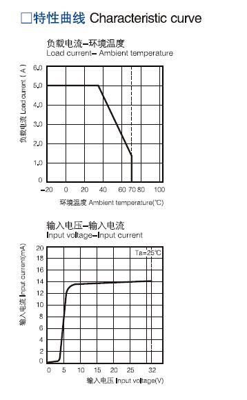
Apply Input Voltage: Use a DC power supply within the SSR’s specified range (e.g., 3–32 VDC).
Measure Input Current: Connect a multimeter in series with the input to check current draw (typical range: 5–30 mA).If the SSR has an indicator LED, verify it illuminates when powered.
Output (Load) Circuit Test
Use a Load and Power Source: Connect a load (e.g., lamp, resistor) and appropriate voltage source to the output terminals.
Activate the SSR: Apply the control voltage. The load should turn on (e.g., lamp lights up).
Deactivate the SSR: Remove control voltage. The load should turn off.
Voltage Measurement:
With control voltage on, measure output voltage; it should match the supply (low voltage drop).
With control voltage off, voltage across the load should be near zero (check for leakage).
Leakage Current Test
Measure Off-State Leakage:
With SSR off, use a multimeter in current mode (µA/mA range) in series with the load.
Leakage should be within datasheet limits (typically <1–2 mA for AC SSRs).
Thermal Evaluation
Monitor Temperature: Run the SSR under load for 10–15 minutes. Abnormal heating indicates internal faults (e.g., shorted components).
Advanced Testing (Optional)
Oscilloscope Analysis: Check switching times and waveform integrity (e.g., zero-crossing behavior in AC SSRs).
Diode Test (DC SSRs): Use a multimeter’s diode mode to verify forward voltage drop when off (body diode) and low resistance when on.
Conclusion
Solid-state relays offer superior performance in speed, reliability, and noise reduction compared to mechanical relays, making them indispensable in modern automation and precision control systems. However, proper selection based on load type, thermal design, and cycle control requirements is critical to maximize their lifespan and efficiency. By understanding their structure, types, and operational nuances, engineers can leverage SSRs to optimize both industrial and consumer applications.