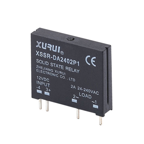
1.When selecting SSRs for use on printed circuit boards with low current specifications, as the lead terminals are made of highly thermally conductive materials, soldering should be carried out at a temperature of less than 250°C and for a period of less than 10S. If necessary, a derating may be considered, taking into account the surrounding temperature, and generally keeping the load current to within 1/2 of the rated value.
2. Various load surge characteristics on the SSR selection of solid state relays
The controlled load will produce a large inrush current at the moment of connection, which is likely to cause damage to the SSR's internal silicon control as the heat is not distributed in time. To ensure that the relay can withstand this inrush current under the premise of steady state operation, refer to Table 2 for the derating factor for various loads (at room temperature).
If the selected relay needs to work more frequently, life and reliability requirements of the higher occasions, it should be based on Table 2 and then multiplied by 0.6 to ensure reliable work.
The above principles are generally followed when selecting a DC solid state relay for low voltage requirements with small signal distortion using a field effect tube as the output device; for example, for AC resistive loads and most inductive loads, a zero crossing relay can be used to extend the life of the load and the relay, and to reduce its own RF interference. If used as a phase output control, random type solid state relays should be used.
3. The effect of ambient temperature
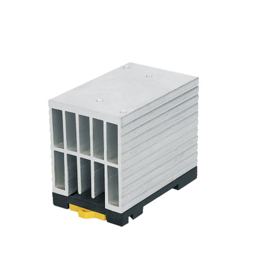
The load capacity of a solid state relay is influenced by the ambient temperature and its own temperature rise. During installation, attention should be paid to good contact between the bottom of the relay and the heat sink, and consideration should be given to applying the appropriate amount of thermally conductive silicone grease to achieve the best heat dissipation effect.
If the relay is working at a high temperature (40°C~80°C) for a long period of time, the user may consider derating the relay to ensure normal operation according to the maximum output current and ambient temperature curve data provided by the manufacturer.
4. Overcurrent and overvoltage protection measures
When the relay is in use, overcurrent and load short circuit will cause permanent damage to the SSR internal output SCR, consider adding a fast fuse and air switch in the control circuit to protect the type (choose the relay should choose the product output protection, built-in varistor absorption circuit and RC buffer, can absorb surge voltage and improve the dv/dt tolerance); can also be connected in parallel with the relay output RC absorption circuit and varistor (MOV) to achieve output protection. The principle of selection is to use 500V-600V varistors for 220V and 800V-900V varistors for 380V.
5. Relay input circuit signal
When using the input voltage is too high or the input current is too large beyond its rated parameters, consider connecting a voltage divider resistor in series with the input terminal or connecting a shunt resistor in parallel with the input port so that the input signal does not exceed its rated parameter value.
6 In the specific use, the control signal and load power requirements are stable, fluctuations should not be greater than 10%, otherwise voltage stabilization measures should be taken.
7. In the installation and use should be away from electromagnetic interference, radio frequency interference sources, to prevent the relay misoperation out of control.
8. When a solid state relay is open and there is voltage at the load end, there will be a certain amount of leakage current at the output end, which should be noted when using or designing.
9. When replacing a solid state relay that has failed, try to use a prototype or a product with identical technical parameters to match the original application line and ensure reliable operation of the system.
AC solid-state relays are available in voltage over-zero conduction (referred to as over-zero) and random conduction (referred to as random) according to the switching mode.
By output switching element, there are two-way silicon controlled output types (common) and one-way silicon controlled anti-parallel types (enhanced).
The pin-and-plug type used on printed circuit boards (natural cooling, no need to bring a heat sink) and the device type fixed to a metal base plate (cooling by a heat sink), according to the installation method.
There are also constant current source types with a wide range of inputs (DC3-32V) and series resistance current limiting types.
SSRs are available in zero-voltage (Z) and phase-modulated (P) versions.